Studio 4B
Overview / Reminder
- Work in groups of 3!
Studio Setup
Follow the steps from Studio 4A! The assignment link is link
Names
Open questions.md and list the names of everyone in your group.
Fulladder: Again
Use task 2.1 to (again) complete a behavioral model of a full adder (you can use work from last studio).
A fulladder adds a single column of digits. A multi-bit adder will require adding several columns and, consequently, can be built by chaining together several full adders. For example (from Wikipedia’s Adder article):

Recall tht you can instantiate existing parts, like the fulladder with syntax something like:
partname instance_name( .part_port(local_signal_to_connect), ... )
For example, an OR gate may have a module definition that looks something like:
module myOr(
    output logic out,
    input logic in0,
    input logic in1
);
   ...
A second module could use it like:
// in My Module
logic ored, soup, salad;
...
myOr anOr(.in0(soup), .in1(salad), .out(ored));
Note:
- This creates a part and clearly associates the names used for the part’s ports (the
out,in0, andin1ofmyOr) to the names of signals in the current module (theored,soup, andsalad).- It would also be possible to rely on the position of signals (
myOr anOr(ored, soup, salad)), but using port names for connections can significantly reduce errors because one can easily read the details of how connections are being made. For example,.clock(clock_a)would clearly indicate thatclock_ais being used to provide theclockto a specific part.
- It would also be possible to rely on the position of signals (
- The example is creating a single
myOrinstance and giving it a name ofanOr. It’s possible to omit the instance name (myOr(ored, soup, salad))- If there were multiple instances (multiple
myOrs) being created, the instance name (likeanOr) can be used when debugging test benches to undertand which signals apply to a specific instance ofmyOr. Using a descriptive instance name is a good proactice.
- If there were multiple instances (multiple
Hint: Constants are commonly used in HDL and can be used directly for inputs. You’ll probably need to use one (er, or zero) here. Often it’s necessary to make sure the number of bits used for a constant matches what is needed. You can review the Verilog Number Formats section of Lecture 4A.
Use task 2.2 to simulate / test your work.
Use task 2.3 to confirm your work via a testbench.
Use task 2.4 to complete question 2.4 in questions.md
Mapping to hardware
Your kits contain an iCE40 UP5k FPGA. Review the Data sheet for the iCE40 UP5K. In particular look at Figure 3.2, whcih describes the “PLBs” in the UP5K. Until now we’ve been using HDLs to depict circuits using digital logic schmatics, which don’t exactly correspond to how the FPGA will be used.
Use task 2.5 to see how our synthesis tools utilize the FPGA. Complete question 2.4 in the questions.md
Multi-bit addition
Use task 3.1 to complete a structural model of a 4-bit adder using 4 instances of your full adder.
Caution!
Be sure to use 4 instances of the fulladder!
Use task 3.2 to simulate your work
Confirm that it can add multi-bit numbers. The inputs and outputs are no longer simple, binary value. Hovering over an input or output will allow you to use the base being used to enter or show that value:
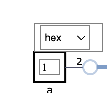
Caution!
You must update values and then click out of the input box for the simulator to use the updated value. (If the cursor is still in the box, it isn’t clear that you are done typing a new value)
Use task 3.3 to verify your work via a testbench
Making it real
Caution!
If you have not already tested using hardware with your computer, please go through the FPGA Programming page!
Windows Caution!
Windows requires a specific device driver to correctly communicate with the UPduino. Installing the driver may be sensitive to both the specific USB port that’s used and/or the specific UPduino that’s used. Please be sure to either use the same hardware and USB port used in the past or reinstall the driver if you encounter errors (See: FPGA Programming).
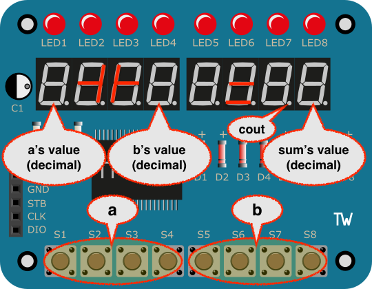
Testing your adder
Task 3.5 creates a bitstream file for your four-bit adder. If done correctly, the left four push buttons will control the left most digit. The right most four push buttons will control the middle digit. Each nibble will be added, using your four-bit adder, and the result will be displayed on the rightmost digit. The carry will be shown in the decimal point of the second digit.
After generating the bitstream, upload it to your UPduino.
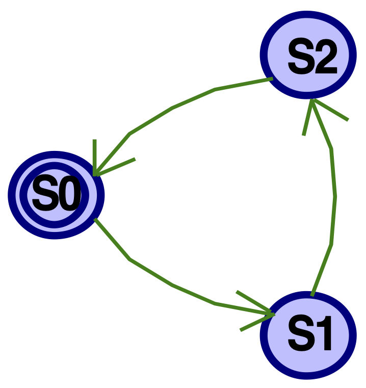
State Machines
statemachine.sv
Complete code for a statemachine that implements the “Every third” behavior covered in class. (Slides). Review the example provided and be sure to use a sensitvity list on reset and clk.
Simulate
Use the simulator to confirm that it works as expected.
A Testbench
Use task 4.3 and 4.4 to complete a test bench to verify that it works correctly.
Warning!
The testbench view that shows waveforms does not automatically update when the testbench is re-run.
- Be sure to close the waveform view before re-running the testbench.
- And/or if, following a testbench run, the waveforms look unchanged, close the waveform view and try one more time to confirm the behavior.
- Be sure to also watch the
Problemstab for potential syntax errors or issues. Sometimes the waveform view may open to prior results if there’s a syntax error.
You may want to review the fulladder testbench (task 2.4). It looks and behaves a lot like a traditional computer program. The initial begin block does define a set of sequential statements. It uses notation like #10 to advance the simulation time. #10 would advance the simulation 10 units of time, #5 would advance it 5 units of time, etc. It uses assignment statements to control the inputs and outputs to parts. It uses $error() tasks to indicate if/when errors occur.
Create a test that controls the reset and clock:
- Use a for-loop, as shown in the
fulladdertestbench, to iterate 10 times. (You may need to add a variable declaration!) - During each iteration:
- Go through a clock cycle and confirm that the output is 0. (It should be in
S0at the top of the loop, so after the first full clock cycle it should be inS1). Use the$error()task to show an error message if it’s incorrect. - Do another clock cycle and again check the output.
- And another.
- Go through a clock cycle and confirm that the output is 0. (It should be in
If your test bench “passes” the first time, change one of the conditions being checked for an error to be deliberately wrong and re-run testbench to confirm the circuit is not behaving as the testbench expects.
Verification: Complete code to verify your work
Deploy to hardware
Task 4.5 creates a bitstream file for your statemachine. You will provide both the reset (reset) and the clock (clk) via buttons and the segements on the rightmost display will light when q is 1:
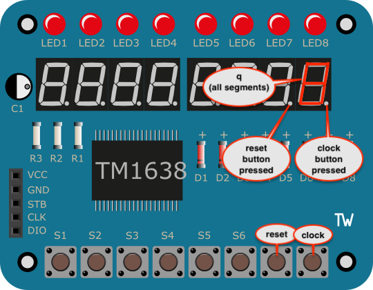
Confirm:
- It starts in the
S0state, whereqis1: The right-most display will show an8whenqis1. (The decimal point on the rightmost digit merely indicates if theclockbutton is currently pressed. The decimal point on the next digit over indicates ifresetis currently pressed) - Repeatedly clocking it causes
qto be1every third time. - Answer question 4.5.
Complete question 4.6 in questions.md
Submission / End-of-class: Commit And Push
1. First, be sure to commit and push files to GitHub (as shown in studio)
1.1
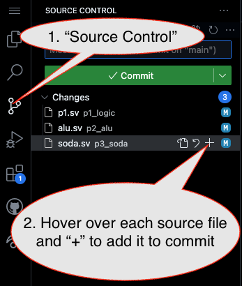
1.2
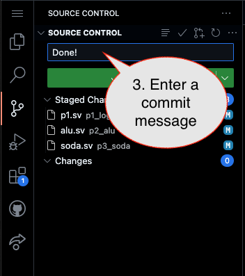
Caution!
Failure to type in a commit message will cause VSCode to open a window to enter the message (in the editor area) and the Source Control pane will appear to be stuck (a waiting animation) until you type in a message and close the message pane.
1.3
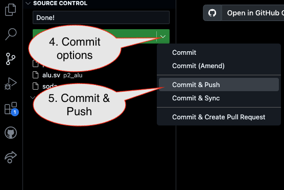
2. Then go to GitHub.com and confirm the updates are on GitHub
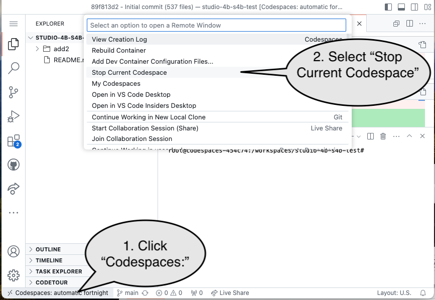
End of Studio: Stop the Codespace
Caution!
Be sure to “stop” your Codespace. You have approximately 60 hours of Codespace time per month. Codespaces often run for ~!5 minutes extra if tabs are just closed.