Studio 5A
Names
Open questions.md and list the names of everyone in your group.
Ripple Carry
Assume a full adder has a propagation delay of exactly $9.999\overline{9}$ units of time on both the sum and carry out. Consider a 4-bit ripple carry adder constructed entirely from instances of this full adder. Assume that at $t=0$ the inputs become $0110$ and $0011$.
Complete question 2.1 in the questions.md
Edit adder.sv and confirm that it represents a ripple-carry adder.
Simulating Propagation Delays in Verilog
Edit fulladder.sv, which is the model of the full adder. The notation #N for numeric values of N can be used to simulate specific delays between operations. For example, #10 would be a delay of 10 units of time (approximately 9.999). You can add a #N after an assigns and before the destination to indicate you want to simulate a delay between the righthand side changing and the assignment to the destination.
This is referred to as a delay control and delays the assignment to the value on the lefthand side:
assign #DELAY DESTINATION = EXPRESSION
Add in a delay of 10 units of time to the full adder.
Edit (Don’t run) adder_tb.sv, a primitive testbench. Note the #100 line, which will introduce a delay of 100 units of simulation time before the next line. Complete question 2.4 in the questions.md
Now run the adder testbench verification and complete question 2.5
The #100 notation introduces a delay in the simulation before advancing to the next line of code. Add in the test case described above after that delay. That is, starting at $t=100$ do $0110_2+0011_2$. Run the testbench and answer question 2.6.
Caution!
You need to close the testbench waveform tab to ensure it refreshes properly.
The testbench window does not automatically update as you change the Verilog files. Be sure to re-run the testbench task.
Storage
ROM
Review the behavior of the rom (Edit rom.sv).
Simulate the ROM and make it output 0x00200000 (in simulation / rom: simulate and without changing the code for it). Complete question 3.1.2 in questions.md
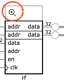
Register File
A “register file” is a way to store and retrieve values. If has “ports” that are used to access and change the stored data. Assume you want to write computer code that would simulate a primitive register file using functions (methods). It should be able to store 32, integer values (int in Java). Complete question 3.1.2.
Review the code given for the register file (Edit regifile.sv). Simulate it (regfile: simulate) and get it to send the content of register 0 (zero) to both outputs. Describe what you needed to do. Note that we can use array-like notation to describe this: we want to retrieve reg[0] on both outputs: rd1 <= reg[0] and rd2 <= reg[0].
Different Register File Implementations!
This register file is suited for a RISC-V processor, which relies on ready access to the value 0. The register file used in Homework 5A doesn’t have to provide such access and has a slightly different implementation.
Try to use the simulator to access other registers and answer Q3.2.3.
Notice the memory element in the simulated circuit, which can be expanded:
Using the memory element expander, manually change the values in reg[4] to 5 and reg[9] to 3. Then using the simulator to do: rd1 = reg[4] and rd2 = reg[9] and confirm that you retrieve 5 and 3.
Using the simulator write the value 7 to register 4 (i.e., via interacting with the inputs while the simulator is running). Complete Q3.2.5.
7-segments
Seven-Segment Displays have long been used in digital logic. As the name suggests, they have “seven segments”, each of which can be “shown” or “not”. Typically a segment is an LED or LCD cell. Enabling and disabling segments can be used to display numbers and even some letters. The segments are typically shaped to facilitate this and are given letters to help identify each one.

(By Uln2003 - Own work, CC0, https://commons.wikimedia.org/w/index.php?curid=69807877)
Your repository contains a display project with corresponding tasks. Edit the display.sv and work through the TODO items one-at-a-time and test each.
Use the Edit top.sv task to review the “top module” in the display project and complete Q4.2.
LED & Key
The LED & Key module is a sequential device. The driver module relies on several concepts we’ve seen this semester. Review ledandkey.sv and complete Q5.1.
The LED & Key module relies on a chip called the TM1638. The data sheet for the TM1638 provides all the details of how it uses it’s clock and data signals.
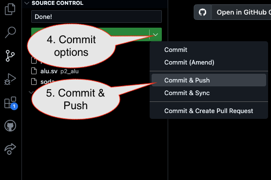
Submission / End-of-class: Commit And Push
1. First, be sure to commit and push files to GitHub (as shown in studio)
1.1
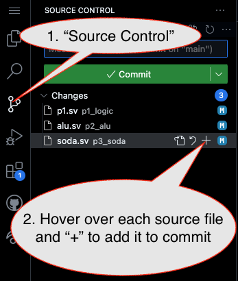
1.2
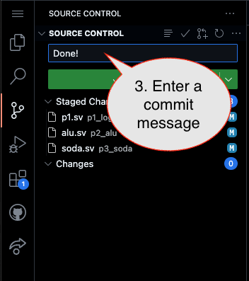
Caution!
Failure to type in a commit message will cause VSCode to open a window to enter the message (in the editor area) and the Source Control pane will appear to be stuck (a waiting animation) until you type in a message and close the message pane.
1.3
2. Then go to GitHub.com and confirm the updates are on GitHub
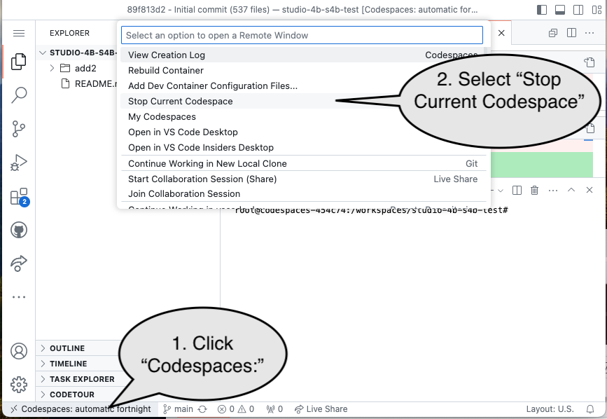
End of Studio: Stop the Codespace
Caution!
Be sure to “stop” your Codespace. You have approximately 60 hours of Codespace time per month. Codespaces often run for ~!5 minutes extra if tabs are just closed.