Homework 6A
Demos!
An in-person demo will be required for full credit. Pay careful attention to the details below to prepare for the in-person demo!
The demo must be completed within 10 days of the due date.
Reminder!
The intent of many assignments/problems is to develop your experience and critical thinking skills, which often is the result of making mistakes and struggling to understand and correct them. The goal is not just submission of a correct solution — we already have solutions to the problems!
The time and work you invest is what has value. Consequently, use of A.I. tools is strictly forbidden on all aspects of this assignment.
Part 1
Conversion to RISC-V Machine Code
Convert each of these to machine code. Show work and the contents of all fields. Show the final result in 8-digit hexadecimal (like 0xABCD1234) with a box around it.
1. sll t0, s0, s1
2. andi s0, s1, 0xFF
3. beq a0, s0, 0x1200 # Assume the imm value should be the 0x1200 shown
Part 2: Assembly Language Programming
General
As is often the case, this includes both some runnable code that will be unit tested and content in questions.md that need to be completed.
Repository
Create a repository for your assignment via: link
Writing Assembly Language
Hints
Assembly language is tedious and error prone. It is always best to:
- When possible, like with
multiply, write and test the code in a programming language that you know. This will help you identify the concepts and critical logic. Assembly language is much easier if you already have correct logic. At the very least you should always have pseudo-code describing your approach. - Once you have an algorithm or pseudocode, make a new copy to add annotations (comments) to that will help you convert it to assembly language. Use concepts from assembly language, like replacing variables with register names. For example, replace
sumwitht2and leave comments that clearly show that every placet2is used it represents the sum. - You’ll need labels for loops and if/else statements. Add in comments indicating where you may need to use labels and what the label will be. Labels are like variable names — they should be descriptive and, although they can be used multiple places, they can only be declared in one place.
- Add comments on individual lines describing instructions that you may need to use to accomplish comparable work in assembly language.
-
Use Indentation: It’s a lot easier to read and follow code that uses indentation in the same way as a high-level language program. Increase indentation on the bodies/statements of loops,
if-statements, etc. - If you attempt to run the simulator and it doesn’t start, that usually means there is a syntax error in your assembly language. Look at the
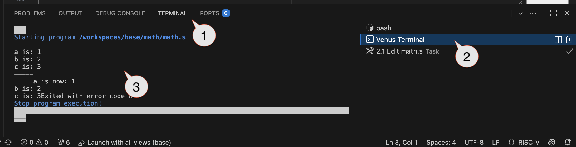
Terminaltab (and, more specifically theVenus Terminal) for errors. - When you encounter problems it may be beneficial to use breakpoints and the debugger to step through test cases. Carefully inspect the contents of registers to confirm values are behaving as you’d expect.
Running and Debugging RISC-V
The video below briefly shows an older version of the “I/O Board”, but all other elements of the video are still relevant.
Demo: The Completed Work
1. Delay function: delay(int ms)
Register Conventions!
This function is a “callee”. You should either: a) only use the registers that are allowed to be changed by a callee (t and some a registers) or b) use the stack to save the old values of any other registers and restore them before returning.
Refer to the section on function calls (6.3.7 and, especially, the sections on the stack and preserved registers).
Extra Hint: This is a “leaf function”. It’ll be best/easiest to only use the a and t registers.
One of the most common places where assembly language is still handwritten is where precise timing is necessary, especially in embedded systems. For example, many types of digital sensors require precise timing for communications. A delay method may be needed to ensure a delay for a required amount of time between changing a signal.
Often such timing depends on a precise understanding of how much time is taken by individual instructions and then constructing a loop that runs enough instructions to consume the required amount of time. However, we’re currently working in a simulator where the timing isn’t very precise. Depending on the specific machine running our Codespace, each instruction in the simulator will typically take between 0.25ms and 2ms (on average).
First we will use an empirical approach to tuning our timing for a delay(int ms) function. The input parameter (a0) will indicate the number of milliseconds of delay that are required. You may assume it will always be greater than 10. Your approach should be accurate within about 10% of the requested value.
- Open
delay.sand start constructing your approach under the assumption that each instruction takes 1ms.- You may only use integer operations, but you may use
mulanddivif needed.
- You may only use integer operations, but you may use
- Try to identify a way to run sufficient instructions to account for the delay described by
a0. (Total code should only be about 5-25 lines). - Run the driver, which will run your code on four test cases. The driver starts with a 1s test, then 5s, then 10s, 20s, 40s, 60s, and 120s. It’s hard to accurately measure short periods of time. Use a stopwatch to try to measure the accuracy of a long delay (you may have an stopwatch app on your phone. For example, the iOS clock app includes a stopwatch, or via google). Based on the measured value, calculate a correction factor and update your code to make this correction.
- Repeatedly adjust your timing approach until you have a method that is typically within 10% accuracy for 20s and higher. You can adjust the test cases on line 4 and 6 of
delay_driver.s(add or remove tests) to focus any debugging or testing. - We’re using the PicoRV32 RISC-V model on our FPGA.
- It’s running with a 6MHz clock.
- The “Clocks” required for each instruction depend on the instruction. See Clocks per Instruction Performance for a list. We are not using dual port registers (use the
CPI (SP)column).
- Answer the questions below in as comments in the designated areas in
delay.sfor the real hardware (data in part 5):- How many clock cycles are needed for one iteration of the loop?
- How much time will one iteration take?
- What formula is needed to compute the number of iterations for 1ms of time?
- Comment out the code for your original “iterations computation” work (which was used in simulation), but leave it in the file. You’ll want it later. Replace it with code that will compute the iterations needed for the actual hardware.
- Use task 1.6.5 to build the firmware for the
delay_driverand test it on the real hardware. If you haven’t already done so, you will first need to program thepico-rv32imc-2600.binon your UPduino (i.e., make it into a RISC-V processor) and then program thedelay.S.fw.binfile (i.e., add the code for the processor to run). - Your calculations should be approximately accurate, but may be off by about 20%. Adjust your formula/computation until it’s within about 10% accuracy.
Tip
The FPGA Loader contains two tabs. Until now we’ve only used Programming to program our devices. The Terminal tab can be used to see the messages printed by the ecalls in the test drivers.
2. Multiply function: multiply(unsigned multiplicand, unsigned multiplier)
Requirements!
Our final processor will not have a mul instruction. For credit you must implement the basic algorithm described below with only integer operations and without using mul or div !
Register Conventions!
This function is a “callee”. You should either: a) only use the registers that are allowed to be changed by a callee (t and some a registers) or b) use the stack to save the old values of any other registers and restore them before returning.
Refer to the section on function calls (6.3.7 and, especially, the sections on the stack and preserved registers).
Multiply should multiply the contents of a0 and a1 using a fast, shift-based multiplication algorithm:
sum = 0
while(multiplier > 0) {
  if(lowest bit of multiplier is a 1) {
    sum = sum + multiplicand
  }
  multiplier = multiplier >> 1
  multiplicand = multiplicand << 1
}
multiply_driver.s contains many test cases, which are listed one per line from line 6 to line 230. As before, you are welcome to adjust the test cases to focus debugging (add more/differnt tests, comment out tests, etc.)
3. Spinner function: spinner(int spins, int segment_time_ms, int digit)
Register Conventions!
This function is both a “callee” and a “caller”. You will need to take special precautions! Refer to the section on function calls (6.3.7 and, especially, the sections on the stack and preserved registers).
If you recall, Homework 4B included a “spinner” element that showed the progress through an individual wash phase. We can also implement this sort of behavior via code. Appropriate behavior will require using your delay method as well as an ecall to set the display. The ecalls used to interact with the UPduino environment are described here. You’ll want to use ecall 0x152.
`delay()` and Simulation!
Temporarily restore your delay() function to use a formula that is appropriate for the simulation!
Complete an implementation of spinner() that behaves as described:
# Parameters
#    a0 the number of "spins" (complete rotations, clockwise around LEDs of a digit)
#    a1  the time to delay with each segment on (in milliseconds)
#    a2  the digit to use (0-3: 0 is rightmost / least significant digit)
# Return value
#    a0  none / undefined
# Side effects
#    Delay for approximately 6*spins*segment_time milliseconds and displaying a pattern on the designated digit
Segments on a display are often numbered from 0-7, which corresponds to their place-value location:
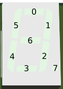
- It should always start with the
0segment of the appropriate digit on. - A full spin ends with segment 5 (total of 6 steps).
- Each segment should be lit for the given delay.
- All segments should be turned off at the end.
- The
a2parameter should allow it to be displayed on any of the rightmost four displays.
Register Conventions!
The Venus Terminal may show error messages if you are violating any of the register conventions. You should avoid such errors!
When done, restore the delay() to work with the actual hardware and use task 3.4 to confirm that your spinner works correctly on the hardware. Be sure to try different durations, digits, and number of spins.
4. Questions: questions.md
As in past assignments, complete the questions in questions.md
Submission
You will need to submit your assignment via Gradescope. There will be two dropboxes:
Part 1, 1-3
As in the past, you need to indicate where your work is for each individual problem.
Part 2, 1-3
As with Homework 4A, you will need to commit and push work to GitHub and then go to Gradescope to “pull” the work over.
- Submission Link: Gradescope