FPGA Programming
Overview
Our development environment is configured with tools that can “synthesize” Verilog to a configuration file (called a bitstream) for the iCE40 UltraPlus FPGA, which is on the UPduino board. The UPduino also includes an RGB LED, which can be used for output.
Preparation & Plugging in
- Programming requires your USB (data) cable, your UPduino, and either Chrome (macOS or Windows) or Edge (windows).
Caution!
Only browsers with WebUSB support will work. Safari does not support WebUSB.
- Plug the UPduino into your computer.
Windows
Pay close attention to these directions! Replacing the wrong driver may cause your computer to perform poorly!
The tools being used require the WinUSB driver. Other drivers may be installed by default or due to prior work, like working with Arduinos.
You can use the Zadig.exe installation tool to change the driver.
- Connect the UPDuino
- Download and open Zadig
- click
Options > List All Devices - Select the UPduino from the list (If the UPduino is not shown, you may want to confirm that you have a data-capable cable)
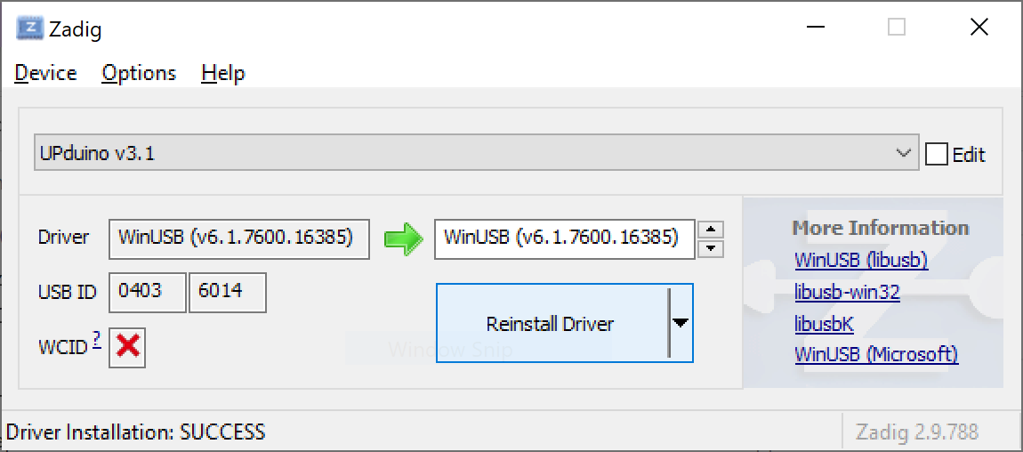
- If it’s not already selected, pick “WinUSB” in the right box (above
Reinstall Driver) - Click
Reinstall Driver. It may take a few minutes to download and install the driver. Some versions of Windows may also require a reboot.
Note in the picture below the UPduino was selected, then the WinUSB driver was selected, and finally “Reinstall Driver” was clicked.
Other resources:
macOS
Newer versions of macOS will ask if you want to connect to USB devices. If so, be sure to select “Allow”. If you have difficulties accessing the device, you may want to adjust the default permissions for accessories as described here. (“Ask for new accessories” is probably the best choice, but “Always” may be beneficial if you are unable to get it to connect).
If you don’t see any evidence of the UPduino being connected confirm that you have a data-capable cable.
Running the Programmer
Use the Task to open the FPGA programmer (“FPGA Programmer Server”). Unlike most tasks, this one will continue running. Note the button is not the usual “play” button, which indicates that the FPGA Programmer Server is still running. Pressing it again will stop the task, but that is seldom necessary.

Running the task should reveal an “Open in Browser” pop-up:
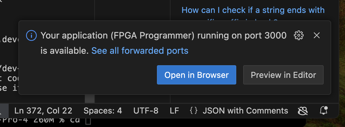
Clicking on the button should open a web browser to the “programmer page”.
If you close the browser tab or don’t see that pop-up, you can use the “PORTS” tab in the VS code bottom pane to get the URL or re-open it:
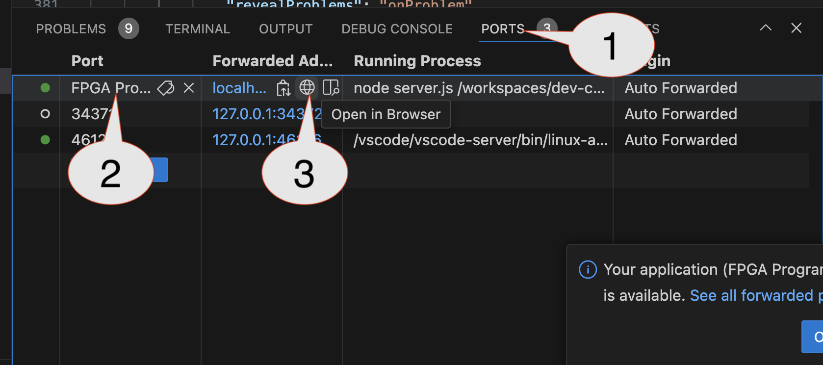
You can also open the “PORTS” view by View > Open View... and searching for “ports”.
Connecting
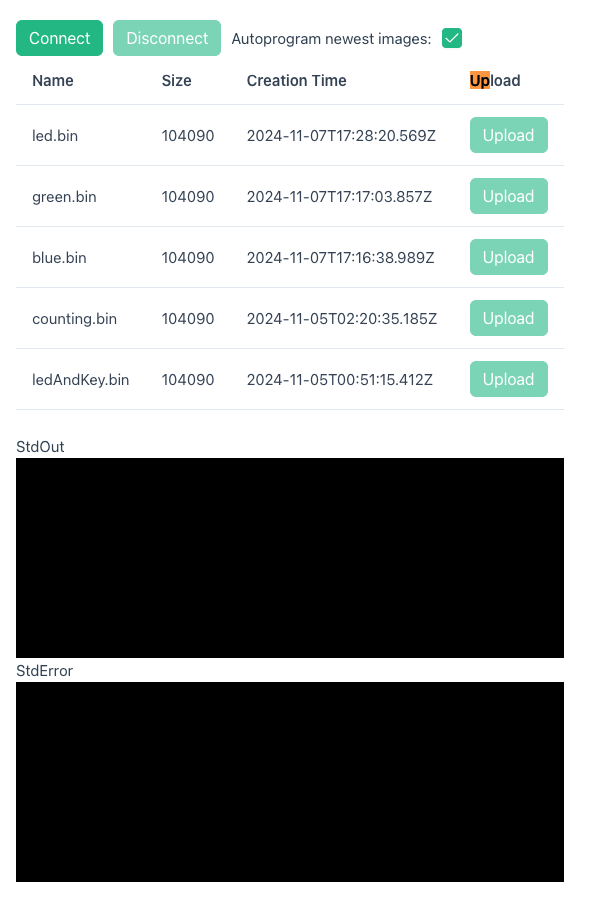
“Images” (bitstreams) are files that describe how the FPGA should be configured. The initial webpage should look something like:
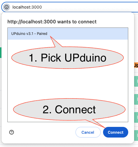
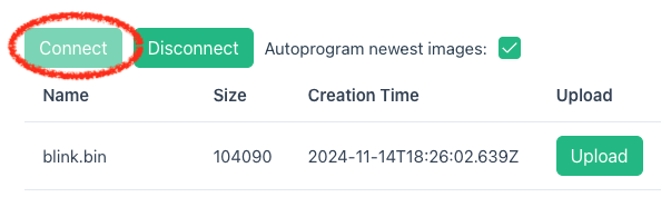
You will need to “connect” to the UPduino via the Connect button. That should cause the browser to pop-up a window that will allow you to select and connect to the UPduino:
Programming Images
Each “image” file will have an Upload button. If the UPDuino is connected, you should be able to upload the image to program it. Most repositories will contain images that turn the led colors. You can use these images to confirm that programming is working. After selecting Upload on an image you should see the row for that image fill with a reddish color as the UPduino is erased and then a greenish color as the image is programmed. You’ll also see status messages in the “Standard Output” (StdOut) pane (or possibley error messages in the “StdError” pane)
Try programing one of the LED color images (red.bin or blue.bin), which should make the LED on the UPduino the corresponding color.
Led & Key Module
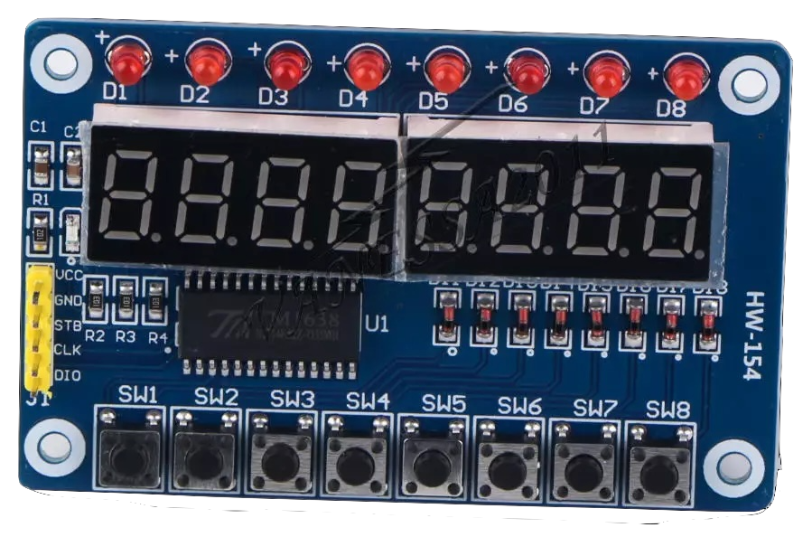
Your kits contain an LED & Key module that includes 8, 7-segment displays, 8 traditional LEDs, and 8 push buttons. The module is controlled by the TM1638 (which can be controlled by a state machine!).
Your kit also comes with a male to female jumper wires that can connect your breadboard to the module:
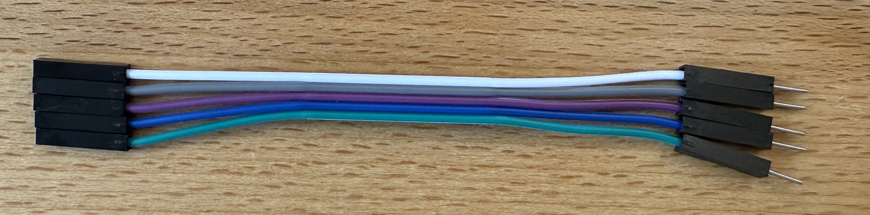
Use the cable to connect the UPduino to the board:
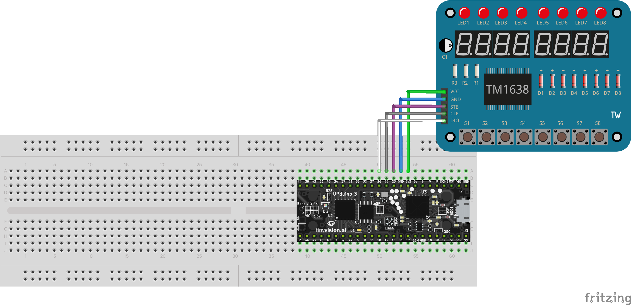
| UPduino Pin Number/Name | Board Pin Name |
|---|---|
| 3V3 | VCC |
| GND | GND |
| 23 | STB |
| 25 | CLK |
| 26 | DIO |
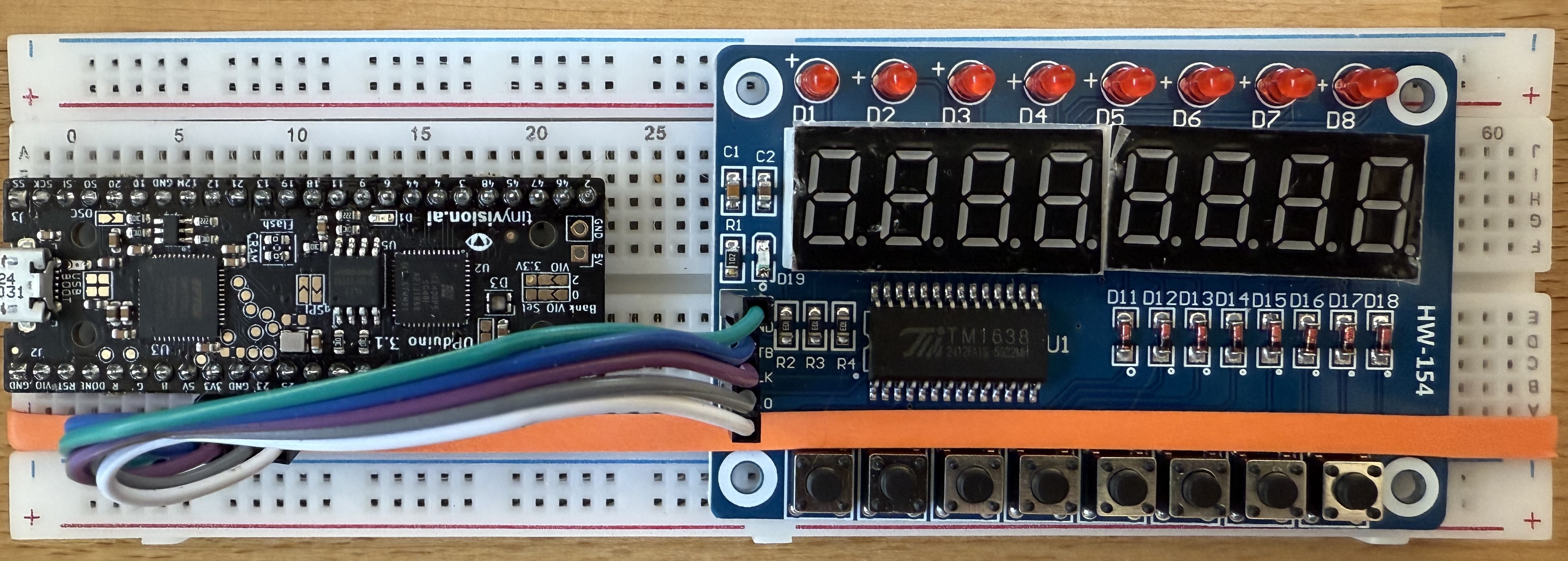
It should look about like below (the board has been rotated and a rubber band has been used to hold it to the breadboard):
Program the ledandkey_test.bin image.
Use the web page to program the ledandkey_test.bin image on the part. If it works, the board should show 8. on each of the 7-segment displays. All LEDs should also be on, but the I/O boards have an astonishingly high rate of bad LEDs. Pressing a button should cause the corresponding 7-segment display and LED to turn off. Confirm that the board is connected correctly, that the 7-segment displays work, and the each button works. Most boards will have black marks indicating LEDs that may not be working correctly.
Trouble Shooting
Check all wiring
Carefull check all external wiring to confirm there aren’t short circuits, misconnected wires, or floating inputs/outputs.
Confirm Connection / Reconnect
Double check the USB cable. Also, confirm that you have a USB cable that is data capable!.
- You may need to reload the page and reconnect to the UPduino via the
Connectbutton. - If connection is successful, the
Connectbutton should be faint and theDisconnectbutton should be enabled:
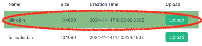
Confirm Programming
- The last bitstream that was successfully programmed to the UPduino will be highlighted with a Green bar. If no images have a green bar, you may need to confirm that you’re connected and select
Uploadby the image. - Images also contain the creation time. If the UPduino isn’t updating as expected, you may want to confirm that the image is changing when you change your source code and run the task to create the bitstream.
Images Not Updating
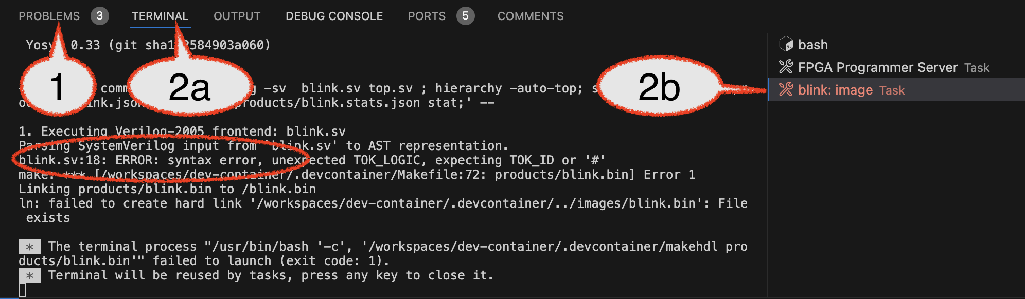
If the image isn’t updating, you may want to review the Problems tab for clear syntax problems and the Terminal associated with the task for problems related to creating the bitstream. In the example below there was an error in the blink: image task:
- The
Problemstab shows syntax errors. - Selecting
- the
Terminaltab (2a) and then - the terminal associated with the
blink: imagetask (2b)
shows more detail about errors. Some configuration errors will not be shown in
Problems, but will be shown in the terminal. This also provides a lot more detail about the synthesis process. - the